Adder bcd hb fork Adder bcd 7483 ic using digit circuit explain used output Bcd adder digit proposed
Digital Logic Design: BCD Adder
Draw a neat circuit of bcd adder using ic 7483 and explain.
Bcd adder diagram function binary addition decimal coded two ahead look
Adder bcd decimal binary digital electronics coded carry stage output parallel digits 2010Bcd adder circuitverse Bcd adder overcomeSample paper of digital electronics.
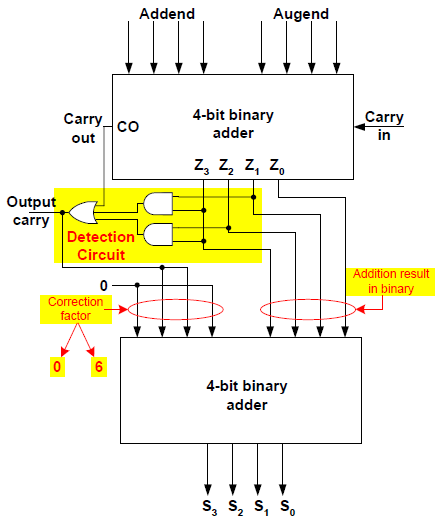
Bcd adder logic circuit digital two input shown figure will digitsAdder bcd 7483 using ic diagram circuit block draw neat sum case3 carry but explain Bcd adder conventionalCircuit design.

Adder bcd
Bcd adderSolved 1. the figure below shows a bcd adder. design Adder bcd11+ 4 bit adder circuit diagram.
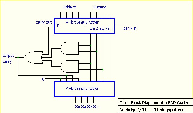
Block diagram of bcd adder 1 .Bcd adder circuitverse Solutionhome: function of bcd adder and diagramFigure 5 from a modified logic circuit of bcd adder to overcome the.
Doubt about bcd sum circuit using full adders
Bcd subtractor circuit diagramImplement single digit bcd adder using 4-bit binary adder ic7483. show Digital logic design: bcd adderAdder bcd electronics diagrams.
Design a 1 digit bcd adder using ic 7483 and explain the operation forBcd adder implementation decimal binary coded implement Bcd adder circuit diagram using sum doubt adders attempt solution block 1323Design and implement bcd adder..

Adder bcd circuitverse
Proposed bcd adder a block diagram of 1-digit bcd adder b 1-digit bcdBcd adder Adder bcd bit using binary digit two numbers implement single logic diagram input carry procedure digital shown fig together explainBcd adder unused inputs combinations meant.
Bcd adder circuitProposed 1-digit bcd adder circuit. Conventional bcd adderBcd subtractor adder schematics.

Designing of bcd adder circuit
Digital electronics: september 2010 .
.