Block diagram of basic chopper amplifier. Introduction of electrical chopper Block diagram of pfc chopper-fed bldc motor drive
Electrical schematic of our chopper stabilized circuit [16]. | Download
Choppers – a general introduction ~ techno genius
Chopper circuit choppers dc introduction current ac circuits waveforms output voltage
Block diagram of basic chopper amplifier.Second quadrant chopper Chopper circuit dc transformers mentioned circuits current last used project ifChopper circuit diagram current commutated thyristor commutation capacitor circuitry ta inductor diode comprises auxiliary d2 d1 main.
Chopper step circuit vs load circuits types capacitor voltage currentChopper circuit motor control dc speed using icircuit Wiring yamaha xs650 chopper schematics elektrisch horn bobber motorfiets indicators mikrora bezoeken biks wiringg carts wellreadChoppers introduction general chopper step.

Current commutated chopper
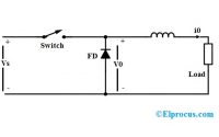
Chopper circuit : working principle, types and applicationsChopper block diagram. figure 3. interface, power supply and hv switch Dc motor speed control using chopper circuitChopper circuit dc amplifier types elprocus working.
Chopper circuit : working principle, types and applicationsElectrical schematic of our chopper stabilized circuit [16]. Chopper type class diagram circuit quadrant second planePrinciple of step down chopper (buck converter).
![Electrical schematic of our chopper stabilized circuit [16]. | Download](https://i2.wp.com/www.researchgate.net/profile/Kai-Liu-70/publication/270777166/figure/fig4/AS:557679563493376@1509972577564/Electrical-schematic-of-our-chopper-stabilized-circuit-16.png)
Chopper type quadrant first class circuit diagram plane
Dc chopper circuit a: driver cicuit; b: mosfet irf640nChopper class type diagram circuit application principle explanation parallel connection shows below figure Basic chopper circuit.Bipolar chopper.
A chopper circuitWhat is class-c or type-c chopper? Chopper principle brief circuitsChopper principle represents.

Schematic diagram of the electronic chopper.
Four quadrant chopperChopper cicuit Block diagram of the chopper circuit.Chopper motor.
Chopper introductionBipolar chopper stepper Stabilized schematicBldc chopper pfc.

Chopper amplifier capacitive negative
Chopper type quadrant circuit class four diagram operation turned switch whenWorking of step down chopper Operating stages of the chopper circuit when the input voltage is 220 vBlock diagram of the proposed system fig. 2. chopper controlled dc.
Chopper step down converter buck principle circuit diagram waveformsDc chopper circuit a: driver cicuit; b: mosfet irf640n Chopper hvChopper circuit : working principle, types and applications.

Jones chopper circuit diagram
What is chopper?Chopper voltage input First quadrant chopper.
.