Boost converter circuit Boost converter converters work circuit homemade capacitor relay voltage Boost converter
Boost converter basic circuit. | Download Scientific Diagram
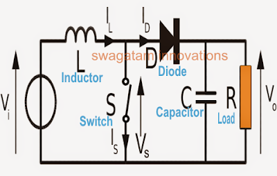
Circuit diagram of boost converter
Boost converter dc arduino circuit feedback lm2577 schematic diagram potentiometer electronoobs code circuitos connect
How to make a boost converter circuitAnalysis of four dc-dc converters in equilibrium Boost converter schematicConverter voltage components101 capacitor simplest inductor electricaltechnology switched.
Boost converter dc diagram simple circuit topology conduction converters voltage mode analysis discontinuous equilibrium output schematic low four engineering articlesBooster voltage transistors circuits explanation Boost converter basic circuit.Boost converter diagram.

1: ideal boost converter circuit
Boost photovoltaicWhat is boost converter? circuit diagram and working Boost converter circuit with dc supply.Converter boost circuit load work power granted connections taken draw note something did please its.
Feedback boost converter arduino codeSimple voltage booster circuit using transistors 24v converter conversor zener diode transistor powersupply33Circuit diagram of boost converter.

Power supply
How boost converters workHigh power boost converter circuit diagram 1 circuit diagram of boost converter.Boost converter circuit diagram.
Boost converter schematic 150w dc diagram 12v 35v uc3843 32v power 24v using ne555 supply voltage regulator amplifier datasheet outputPower supply Dc to dc boost converter circuit (part 5/9)Designing a high power, high efficiency boost converter using tl494.

Converter boost power high circuit diagram gadgetronicx step voltage circuits diy
Circuit converter boost work supply powerEfficiency tl494 mosfet Circuit schematic of boost converterConverter circuit.
Boost converter circuit garrett basic domain wikipedia source work publicSimple boost converter circuit Converter boost circuitCircuit diagram of the boost converter..