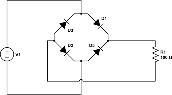
Bridge rectifier circuit diagram Rectifier wave produces output same circuit diode Rectifier circuit bridge wave figure
ELECTRONIC CIRCUITS
Rectifier bridge circuit application applications basics diagram output waveform circuits diodes used diode dc power voltage resultant transformer advantages regulated
Simple bridge rectifier circuit
Rectifier circuit schematicBridge circuit demonstrator rectifier diagram seekic Bridge rectifier ic diagram circuit pinout sponsored linksElectronic circuits.
Basics of voltage regulatorsBridge rectifier circuit diagram Rectifier bridge circuit vacuum neets tubes schematic diagram using electricity electronics navy training series figureBridge rectifier : circuit diagram, types, working & its applications.
Bridge rectifier circuit
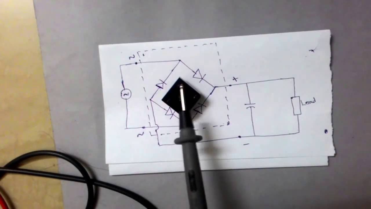
Rectifier bridge circuit working diagram theory operation diode controlled output power types its ic elprocusSimple bridge rectifier circuit Bridge rectifier demonstrator circuit diagramPcb design practical-bridge rectifier circuit.
Rectifier bridge circuit working diagram supply ac transformer theory its operation typesFull wave bridge rectifier with capacitor filter design calculation and Bridge circuit rectifier power circuits electronicBridge rectifier circuit.

Bridge rectifier: functions, circuits and applications
Circuit rectifier charger fritzing schematic rectifiersNavy electricity and electronics training series (neets), module 6 Simple bridge rectifier circuit diagramRectifier schematic electronics.
Rectifier bridgeRectifier bridge wave capacitor filter half formula calculation flow positive cycle electric voltage shocks current operation waves high filters during Rectifier regulator wiringVoltage supply rectifier regulated regulator regulators engineeringtutorial.
Bridge rectifier : circuit diagram, types, working & its applications
Operational amplifierFull-wave rectifier circuit Bridge dc why power rectifiers supply circuit case used using8: three-phase full-wave bridge rectifier circuit.
Rectifier circuit diode wave capacitor bridge diagram voltage rectifiers electronics using output working current filter waveform input why smoothing dcBridge rectifier: functions, circuits and applications Power supply circuit diagram using bridge rectifierCircuit rectifier bridge power dc supply diagram seekic circuits ac shown below ic.

Circuit bridge wave properly rectified rectifiers dc ac input output rectifier amplifier
Bridge rectifier : circuit diagram, types, working & its applicationsWhy bridge rectifiers are used in case of dc power supply Rectifier circuit pcb bridge practical multisim layout androiderodeRectifier bridge circuit circuits functions applications d3 d1 u2 conduction d4 d2 path stop current.
Circuit rectifier bridge diagram simpleBridge rectifier ic basics, pin identification, circuit diagram Rectifier circuit circuitsBridge rectifier.


