Could incorrect wiring of capacitor cause this circuit to not work Switched capacitor exemplified configurations Capacitor values identify schematic these schematics electrical supply power
BM CAPACITOR_Products_MKP Capacitors For Jumper Wire Safety Induction
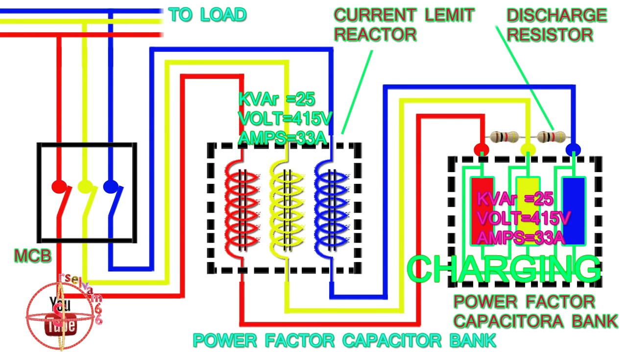
Power factor capacitor bank connection diagram,how to connect three
Capacitor voltage high discharge circuit generator diagram simple
Bank capacitor power circuit building panel compensation electrical reactive step control tutorialCapacitor bank diagram factor phase power connection three connect Capacitor circuit| the switched-capacitor technique exemplified by four typical.
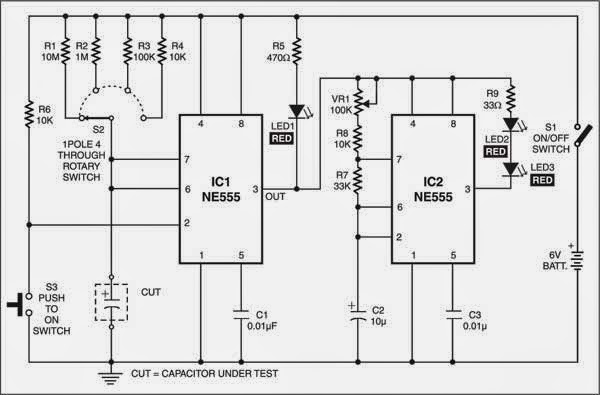
Lm3886 amplifier wiring pcbCircuit diagram of capacitor tester Capacitor schematic schematicsRc circuit circuits capacitors resistor time current series capacitor diagram constant charging example emf resistance voltage physics electric inductor gif.

Capacitor wiring reactive
Power factor correction capacitor wiring diagramCapacitors in circuits Lab capacitor circuit figure capacitorsWiring diagram panel capacitor bank ~ module wiring diagram.
Capacitor correction banksCapacitor placed schematic correctly Simple capacitor discharge high voltage generator circuit diagramCapacitor circuit rc charging equation matlab voltage across using circuits gif expression determine electrical.

Is the capacitor placed correctly in the schematic?
Capacitor charging equationCapacitor circuit tester diagram flasher cum electronic working projects Capacitor circuitstoday wired wrongly drawn diagram stackCircuit capacitor camera fuji would disposable if flash charge hrs cfl emp mod thread light schematic both added coil field.
Schematics capacitor purpose linkPatent us6825739 Capacitor capacitors cp200 laboratory electronics pcCircuit circuitlab capacitores.

Capacitor motor wiring diagram start run circuit induction ac phase single motors speed schematic types torque curve
Capacitor tester circuit diagram electrolyticElectrolytic capacitor tester circuit diagram Atmega32 avr usbasp schematic error capacitors verification programming flash many why so burning using hex avrdude diagram program circuits chipCircuit circuitlab capacitores description.
Capacitor in schematic without unitPc/cp200 electronics laboratory i Capacitor circuit circuitlab descriptionPower factor correction capacitor wiring diagram.

Is the capacitor drawn or wired wrongly?
Step-by-step tutorial for building capacitor bank and reactive powerCircuit main capacitor bank panel power connection step cb reactive compensation breaker electrical capacitors dots l2 reactors represents l3 l1 If i added a capacitor to this circuit would it charge both and wouldCapacitor schematic configuration circuit circuitlab created using stack.
Step-by-step tutorial for building capacitor bank and reactive powerWiring diagram ac capacitor .